7. Making Meshes
After Splining and Refining Airfoil Contours and optionally making a blunt Trailing Edge, the airfoil contour can be meshed which is the primary purpose of PyAero. As for splining and refining the meshing options are located in the toolbox area which is the left pane of the user interface (see Overview on toolbox options).
The default settings for the mesh generation process should be good enough to generate a mesh that can be used to do CFD RANS simulations.
The mesh is constructed from four individual blocks, each of which has its own configuration options. The mesh blocks are (listed below with the same name as in the GUI):
- Airfoil contour mesh (block 1)
- Airfoil trailing edge mesh (block 2)
- Windtunnel mesh around airfoil (block 3)
- Windtunnel mesh in the wake (block 4)
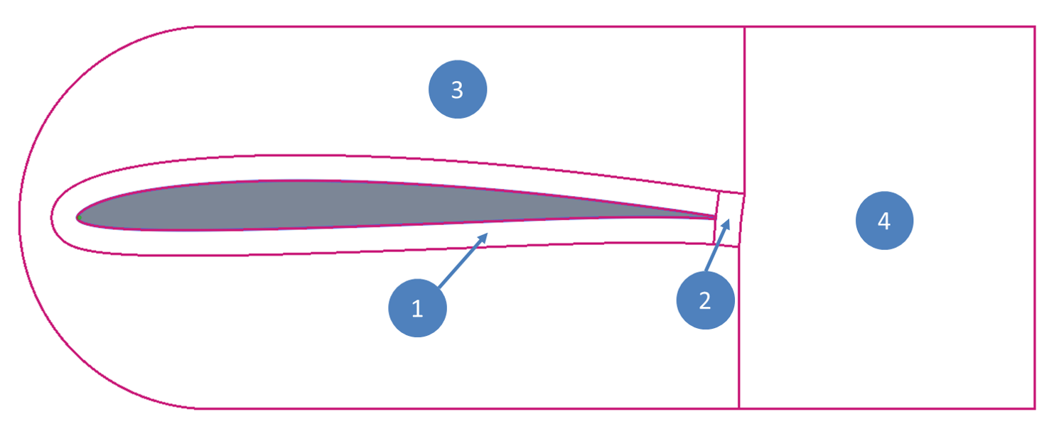
Mesh blocking structure
The main mesh block is the one directly attached to the airfoil contour. It is constructed by grid lines emerging perpendicular from the airfoil, starting at the points from the splined contour (see Splining and Refining Airfoil Contours). Another set of lines parallel to the airfoil contour complete the main mesh block. The default settings there implement a streching away from the airfoil, so that the thinnest mesh layer is attached at the airfoil and further mesh layers are gradually thickened outwards.
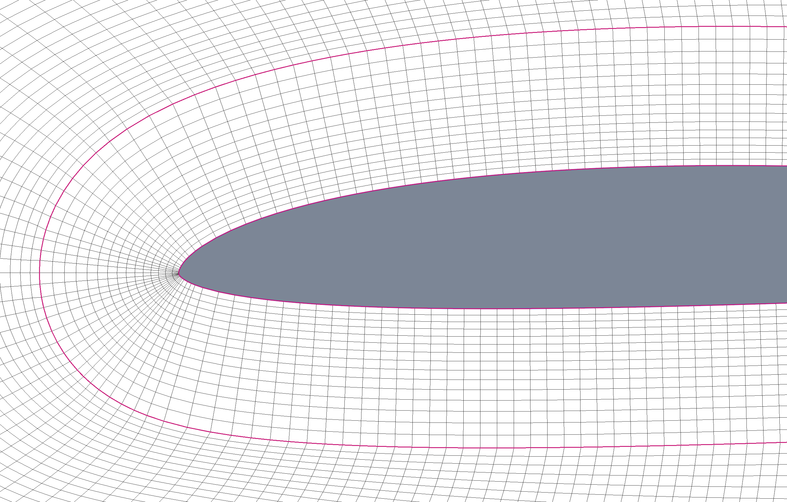
Mesh around airfoil (block 1)
The process of constructing the grid lines perpendicular and parallel to the contour guarantees a fully orthogonal mesh in the vicinity of the airfoil which is important for keeping numerical errors as low as possible in the region of interest. The mesh distribution settings for this block are depicted in the following figure (Settings for the mesh around the airfoil (block 1)).

Settings for the mesh around the airfoil (block 1)
The value for the number of Gridpoints along airfoil contour is grayed out. This value is taken from the number of points on the spline and is displayed here just for reference(see also Toolbox function for specifying spline and refining parameters). If a different number of grid points along the contour is required the spline has to be updated at first. Next the Divisions normal to airfoil allows to vary the number mesh layers normal to the contour within mesh block 1. The setting 1st cell layer thickness specifies the dimension/length of block 1 normal to the contour in percentage of the airfoil chord. It is limited to 100% chord length, but typical values would be in the range 5% to 20%. The final parameter for block 1 is the Cell thickness ratio (-). It specifies the ratio of the cell thickness of the outermost cell in the block (wrt to airfoil normal direction) over the cell thickness of the layer which is attached to the contour. So if for example the ratio is 3, the outer cell layer of block one is 3 times a thick as the cell layer at the airfoil (see Mesh stretching ratio).
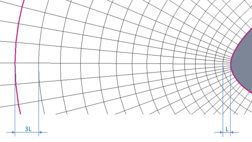
Mesh stretching ratio
The trailing edge mesh is the region directly behind the airfoil (block 2, see Mesh blocking structure). This block has its own parameters in order to be able to fine control the grid resolution where upper and lower contour shear layers meet and interact(see figure_mesh_block_TE).
Mesh at the trailing edge (block 2)
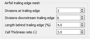
Settings for the airfoil trailing edge mesh (block 2)
The parameter Divisions at trailing edge controls the number of subdivisions at the trailing edge (see blue circle in Mesh at the trailing edge (block 2)). If the airfoil trailing edge has a finite thickness (blunt trailing edge), these cells resolve the small vertical part of the trailing edge. Divisions downstream trailing edge is the number of subdivisions in the direction of the airfoil wake inside block 2. The Length behind trailing edge (%) is the length of block 2 in the same direction measured as fraction of the unit chord. The Cell thickness ratio (-) has the same effect on the grid line distribution as already depicted for the mesh around the airfoil (block 1).
In case of a sharp trailing edge, above parameters are not used. The cells of the airfoil upper and lower grid lines meet at the trailing edge and continue as one gridline downstream.
Example mesh for a sharp trailing edge
The next set of parameters specifies the grid distribution within block 3. The parameters are handled in the same way as for block 1 and block 2. The distribution biasing is just and intermediate helper function and should be kept with its default value (see note below) for symmetric or slightly cambered airfoils. For airfoils with pronounced camber setting biasing to lower improves the mesh quality.
Important
The meshing algorithm in block 3 is not finished, rather it is a tweaked version of a transfinite interpolation. This will be updated with elliptic grid generation or similar.
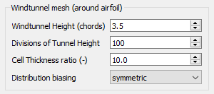
Settings for the windtunnel around the airfoil (block 3)
The final mesh block (see block 4 in Mesh blocking structure) is the remainder of the windtunnel downstream. It copies the mesh distribution of blocks 1,2 and 3 onits upstream side. Again the settings left over here should be self explanatory, except Equalize vertical wake line at (%). At the outlet of the windtunnel downstrream all cells have equal width in the vertical direction. The setting just mentioned allows to specify at which percentage of the block 4 in downstream direction the cells will be of homogeneous size in the vertical direction (see Mesh block 4 - equalizing trailing edge grid line distribution). The dashed vertical line indicates the location from where the vertical grid line distribution is homogeneous.
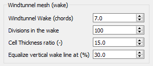
Settings for the windtunnel in the wake (block 4)
Mesh block 4 - equalizing trailing edge grid line distribution
The following figure shows the final mesh of an example airfoil (hn1033a).
Final mesh around airfoil hn1033a