6. Trailing Edge
Note
If a sharp trailing edge is needed, this step can to be skipped.
As outlined in the section before, the meshing process relies on the point distribution on the airfoil contour. Real airfoils, i.e. airfoils which are built as a hardware, have a trailing edge (TE) with a definite thickness, a blunt trailing edge. This is due to manufacturing and/or structural reasons. To be able to model this, PyAero has a dedicated function. The following figure shows an animation of a sharp trailing edge and a blunt trailing edge.
Sharp and blunt trailing edges
The blunt trailing edge needs to be added to the original contour in a controlled manner. The parameters shown in the following figure can be used to control this process.
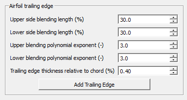
Toolbox function for specifying the blunt TE blending parameters
The trailing edge thickness itself can be specified relative to the unit chord. The thickenning is done perpendicular to the camber line at the trailing edge. In order to prevent aerodynamic artefacts due to the blunt TE, a smooth controlled blend from the blunt TE vertices into the original (raw) contour needs to be done.
This is achieved by allowing to blend along a certain user specified length into the original contour. Furthermore, the degree of the blending curve can be specified. The blending length describes the fraction (in %) of the chord in which the blending is done. The polynomial exponent can be used to describe the blending curve degree. The blending can be controlled individually for the upper and lower sides of the contour. This is specifically useful for strongly camber airfoils.
To better understand the TE blending options the following figure depicts a visually exaggerated TE blending (by clicking several times on the Add Trailing Edge button). The upper side of the aifoil is blended over 50% of the chord with a linear blend, whereas the lower side is blended over 20% of the chord with a polynom of degree three.
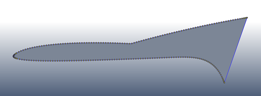
Exaggerated TE blending: 50% linear (upper), 30% 3rd order polynom (lower)
Playing with the settings and finding the best setup for blending is always best viewed by clicking two or three times on the Add Trailing Edge button. A reset to the original curve can be achieved by simply clicking on the Spline and Refine button in the menu above (see Toolbox function for specifying spline and refining parameters).
When a satisfying result is achieved for the contour in terms of splining, refining and trailing edge, the meshing process can be started.